auszookers.com
https://auszookers.com/forum/

GV CrossMember
https://auszookers.com/forum/viewtopic.php?f=14&t=31207
Page 1 of 4

Author:  Built4thrashing [ Thu Mar 15, 2012 8:35 pm ]
Post subject:  GV CrossMember

After destroying the gearbox cross member once again i decided to start making my own.

Image

First i made a template with some 16mm pipe.

Image


Once it was the right shape i took it to my sheetmetal place and got them to fold up a bit of 140x5mm plate.
Had to adjust the folds a little but it now fits nicely

Image

Tack welded in some gussets for added strength


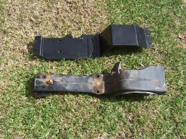
Compared to the factory one ive gained about 40mm extra clearance

Image

Will send it back to sheet metal place to finish off the welding and to also weld in some extra strengthening ribs on the top side.

Image


Once its finished ill prob send it off to be powder coated but knowing me ill just spray pack it and forget about it.

Author:  Joe [ Thu Mar 15, 2012 9:20 pm ]
Post subject:  Re: GV CrossMember

:youdaman: :goodjob:

Author:  shabz [ Thu Mar 15, 2012 9:45 pm ]
Post subject:  Re: GV CrossMember

Nice work 8)

Author:  Built4thrashing [ Fri Mar 16, 2012 6:02 am ]
Post subject:  Re: GV CrossMember

Let me know if your keen on one as I may get a few made. Cost will be around the $120 mark I hope.

Author:  christover1 [ Fri Mar 16, 2012 8:36 am ]
Post subject:  Re: GV CrossMember

I like it, brilliant work.
Won't be long before mines gets hammered

Author:  Built4thrashing [ Fri Mar 16, 2012 4:23 pm ]
Post subject:  Re: GV CrossMember

Tack welded in some braces to the top side today so its now ready to be properly welded up.

Image

Plan is to test fit it to a mates GV to make sure my mounts are not bent.

Author:  PJ.zook [ Sat Mar 17, 2012 9:12 am ]
Post subject:  Re: GV CrossMember

Bring it round if you want it welded up.

Author:  Gwagensteve [ Sat Mar 17, 2012 10:26 am ]
Post subject:  Re: GV CrossMember

Nice work so far, but IMHO this is far from finished - it needs more attention to the positioning of the gussets. As it is, that's far less resistant to bending than the stock crossmember which is a box section right to the ends.

As far as I can see there is no reason for the gussets on the top section to stop short of the nuts. As it is, there's going to be a lot of force concentrated between the foot of the gearbox mount and the commencement of the gussets, and between the gussets and the bolt holes. Sit the car on the crossmember and it's going to bend in the middle under the gearbox.

Please take this as constructive criticism - you've done a great job so far.

Steve.

Author:  Built4thrashing [ Sat Mar 17, 2012 7:50 pm ]
Post subject:  Re: GV CrossMember

Originally i had thought the same thing but the idea is to have the top gussets/ribs on top as to reduce what will catch on them. The stock crossmember is quite strong but that is only due to its shape. Its only made of very thin sheet metal. 2mm at best. The next thing to go with the crossmember is a skid plate to protect the t/case and that will be more likely to get hit rather than the crossmember.More on that another time.

Author:  Built4thrashing [ Sat Mar 17, 2012 7:54 pm ]
Post subject:  Re: GV CrossMember

more pics of it mounted.

Image


Image


Image


Image

Author:  jdk81 [ Sat Mar 17, 2012 8:34 pm ]
Post subject:  Re: GV CrossMember

+1 to what steve said.

What you have made is significantly weaker than what was there from factory.
I attached the drawing of where plastic hinges will form, you will either see it start to bend or you will get fatigue cracks here.

The factory x member, was designed for a certain strength. You appear to have reduced the strength considerably, protecting the vehicle from taking impacts in that area is one thing, but you need to maintain design strength.

If you can provide a rough x-section of the factory (rough sketch with dimensions will do), I will work out an approximate moment of inertia (I).
This will be the design moment of inertia we need to achieve.

I am expecting we can add a few small guessets, whilst keeping the clearance suitable.

Author:  atari4x4 [ Sat Mar 17, 2012 9:06 pm ]
Post subject:  Re: GV CrossMember

looks very similar to the one in mine, it does have a folded edge for bracing/strength. came from FTS or GIZ via ODA, been in there fore about 3 years & it's still in 1 piece.

old VS new
Image

Image

Image

Author:  gvzookdriver [ Sat Mar 17, 2012 9:32 pm ]
Post subject:  Re: GV CrossMember

So could B4T just weld a strip at right angles along the edge like the GIZ one would this fix the problem that everyone is talking about ??

Author:  atari4x4 [ Sat Mar 17, 2012 10:01 pm ]
Post subject:  Re: GV CrossMember

yeah something like that would be plenty IMO.

Author:  Gwagensteve [ Sun Mar 18, 2012 6:50 am ]
Post subject:  Re: GV CrossMember

atari4x4 wrote:
yeah something like that would be plenty IMO.


X2. That would fix the problem.

Steve.

Author:  jdk81 [ Sun Mar 18, 2012 7:22 am ]
Post subject:  Re: GV CrossMember

I like in the one atari has, they added the plate, so that they could then counter sink the gearbox bolts.

The cross member atari replaced on his (J20A), has a much smaller cross section. It appears the gearbox mount has been made significantly stronger by Suzuki for the GV (H25A).
I dont know why Suzuki made the GV so different, but I feel it is an appropriate design strength to aim towards.

Author:  Built4thrashing [ Sun Mar 18, 2012 7:29 am ]
Post subject:  Re: GV CrossMember

I can see a majour issue with the one atari has...... Where have half the mounting holes gone?

Plus the added strength they needed i think is due to the V6 motors.


Thanks for the input guys. I spoke to a few people about where to add strength to the design and they all think it would be fine just as it is. The ribs continue right up to the edges of the mounts and even tho it might be the weakest point it is extremely unlikely to get hit by or smashed against rocks. You'd be more worried about the back of the transfer as it is sitting 30mm lower.

This is only a first attempt at making it and ill be doing a few other versions untill im happy with the end result.

Author:  Built4thrashing [ Sun Mar 18, 2012 7:48 am ]
Post subject:  Re: GV CrossMember

I think if i was to add more bracing i would add it where the red lines are. and maybe one underneath where the purple line is...


Image

Author:  ajsr [ Sun Mar 18, 2012 7:51 am ]
Post subject:  Re: GV CrossMember

that would help alot, I tend to agree with the others, it will crack at the ends of the ribs otherwise. I would still make the other ones run all the way through and extend the bracing on the sides. IMO

Author:  Gwagensteve [ Sun Mar 18, 2012 7:57 am ]
Post subject:  Re: GV CrossMember

I don't think it will crack, jut bend through the middle.

anyway - what AJSR said.

Steve.

Author:  jdk81 [ Sun Mar 18, 2012 8:05 am ]
Post subject:  Re: GV CrossMember

Once again, if you can give me some x section measurements where I indicated. Better yet, the measurements where the cross section is the largest (rough sketch with dimensions).

I can tell you how much guessetting you will need. This will remove all guess work.

Author:  Built4thrashing [ Sun Mar 18, 2012 8:19 am ]
Post subject:  Re: GV CrossMember

My factory cross member is not exactly in its original shape thus the reason why ive had to make a new one...

Ill see if i can get some measurements and PM you the drawings.

Author:  jdk81 [ Sun Mar 18, 2012 8:23 am ]
Post subject:  Re: GV CrossMember

thatd be swell

Author:  Built4thrashing [ Sun Mar 18, 2012 8:49 am ]
Post subject:  Re: GV CrossMember

jdk81 wrote:
thatd be swell


You have PM

Author:  Built4thrashing [ Sun Mar 18, 2012 8:51 am ]
Post subject:  Re: GV CrossMember

For those interested here is a hand scetch of the cross section profile of the factory crossmember.....measurements are a bit of a guess as its no longer straight.

Image

Author:  jdk81 [ Sun Mar 18, 2012 12:18 pm ]
Post subject:  Re: GV CrossMember

I cant comment much atm I had a few incidents, I calcd by hand then confirmed with solid works.
My 2yr old draw all over my work whilst making lunch, then there was the fork in the eye tragedy of 2012. Now im trying to get her to sleep.
I used the top drawing as the basis for work, as its the strongest.

You can simplify it to an I beam, and its considerably strong, after calculating I wasnt expecting it to be that strong.
With your 5mm plate, you need to attach 6 gussets 5m wide X 35mm high, to achieve the same strength.
Obviously this will change, If you can give me some more measurements of where theres space etc, we can improve on this.

It was considerably weaker, yet I suspect your new one is greater mass.

Author:  jdk81 [ Sun Mar 18, 2012 12:28 pm ]
Post subject:  Re: GV CrossMember

FWIW i used hand calcs to confirm a spreadsheet calc, then did all the work in spreadsheet.
I used solidworks to draw the shape, and forgot about the properties feature.... im such a tard.
And solidworks does conform with spreadsheet calcs.

Author:  atari4x4 [ Sun Mar 18, 2012 12:34 pm ]
Post subject:  Re: GV CrossMember

Built4thrashing wrote:
Plus the added strength they needed i think is due to the V6 motors

Image


the GV v6 one looks identical to the stock one out of my vitara

Image

Author:  Built4thrashing [ Sun Mar 18, 2012 12:36 pm ]
Post subject:  Re: GV CrossMember

Thats about what mine was like but it was more than just the sides that were bent...


jdk81...... None of those figures mean anything to me as im not in this field.....can you dumb it down a bit for us and explain what the figures relate to?

Thanx

Author:  jdk81 [ Sun Mar 18, 2012 12:41 pm ]
Post subject:  Re: GV CrossMember

basically you need 6 gussets 5 mm wide 35mm high welded on your plate.
The pic with the plate and solid chunk comes up, indicates how much material you need to add pointing up, if you only go 35mm high off the top of the plate.

Or cap the ends with 2 15 mm wide and 35mm high off top of plate. (same amount of material as before).

If you can go higher, you can remove a lot of material.

It seems extreme because you have no real strenght in the plane required. (essentially you have replaced an i beam with a plate)

Page 1 of 4 All times are UTC + 9:30 hours
Powered by phpBB® Forum Software © phpBB Group
https://www.phpbb.com/