| Author |
Message |
Highway-Star


Joined: Thu Apr 30, 2009 11:30 pm Posts: 4109 Location: Ipswich
Vehicle: LJ80V-II (a proper Stockman)

|
 Posted: Tue Apr 05, 2011 9:23 am |
|
OK, I started doing this to try and figure out the minimum distance I had to make the chassis brackets apart for a Jeep spring swap on the back of an LJ81 using Suzuki standard shackles. Considering I have seen a few RUF's go wrong, and a few types of lifted springs being too long for standard hanger positions, I thought I'd throw this out there for possible use, or discussion...
(before reading any of this, be aware of manufacturing differences, so measurements of components may differ!).
I figured I didn't need to simulate this super accurately, so I just treated the suspension geometry as a regular triangle.
The main leaf being side L (actually distance from eye to eye)
The shackle being side S (pin to pin)
and side C being the straight line distance between the shackle hanger and spring hanger on the chassis.
This of course is for the spring being totally flat, which is when the spring stands its biggest chance of inverting anyway.
A simple Theoretical model:
The most simplest dumbed down theory would be, when S+C =< L, inversion will occur. This however is crap, as it tells you very little information.
Instead I wanted to find out what the shackle angle would be with certain geometries. So using the law of cosines (click here if you don't know it), I rearranged it to get a way of determining the angle between the shackle and the main leaf when the leaf spring is flat.
A = arcos((L^2 + S^2 - C^2)/(2LS))
'A' being the angle. If the angle is 90 degrees, then your shackle is 90 degrees to your leaf spring, which is close to vertical on the front of a leaf sprung Suzuki (close enough anyway). If the angle is 0 degrees, it will invert; If you get a mathematical impossibility, then it will definitely invert! 
Standard Suspension:
Front: L = 940mm, C = 910mm, S = 70mm........ A = 63 degrees.
Rear: L = 1000mm, C = 975mm, S = 70mm........ A = 67 degrees.
This shows why longer aftermarket springs are feasible, the angles are large (ie closer to vertical). Take one of the longer aftermarket rear leaves which causes inversion problems on some vehicles.... EFS.
EFS Rear: L = 1040mm, C = 975mm, S = 70mm........ A = 21 degrees.
A much much flatter shackle when the leaf spring is flat. However it is not 0 degrees, so why do they invert on some cars? The answer has to be spring bushes.
Accounting for Spring Bush compression:
I don't know typical stiffness values for spring bushes, but I wanted to make sure when I get around to welding brackets on the chassis, inversion is not going to be possible. So I went conservative, and assumed there were no spring bushes left in the shackle.
Introducing a new parameter, I'll call B for bush.....
B is the thickness of spring bush between the centre pin and the leaf or chassis eye. For a small size Suzuki bush this is about 8mm, 17mm for a large type bush. Add B to the effective L, and subtract from the effective C, to represent non existant spring bushes, and the shackle pins pushing hard against the outside of the eyes.
A = arcos(((L+B)^2 + S^2 - (C-B)^2)/(2(L-B)S))
Above examples redone:
Front: L = 940mm, C = 910mm, S = 70mm, B = 8mm........ A = 47 degrees.
Rear: L = 1000mm, C = 975mm, S = 70mm, B = 8mm........ A = 53 degrees.
EFS Rear: L = 1040mm, C = 975mm, S = 70mm, B = 8mm........ A = Not possible, ie will invert.
If the rear chassis bracket spacing was changed to 986mm, the EFS rear attained an angle of 0 degrees, meaning a C of greater than 986mm would not be able to invert one of these springs. I have measured one WT Sierra chassis with rear spacing of ~985mm which is close, and considering total failure of the spring bushes to the extent I am assuming is unlikely, these 985mm chassis would probably be fine.
Its also worth noting I run these springs on the back of my LJ80 which definitely has 975mm chassis bracket spacing, and they cannot quite invert. The reason for this is I have extended bumpstops which don't allow the leaf spring to completely flatten out (just something else to consider).
Anyway the numbers I was originally after:
Jeep CJ-7 front springs
I did some buggerising around in excel using these little relations, and came up with this:
CJ-7: L = 1130mm, C = 1075mm, S = 70mm, B = 6.5mm........
A = 37mm without spring bush deformation
A = 13 degrees without spring bushes.
So I got 1075mm as a minimum chassis distance (to the nearest 5mm) which won't invert a spring. The CJ-7 chassis uses about 1032mm from what I have found, but I believe they use longer shackles...
This is the minimum value, I could make the distance slightly larger to maintain a more vertical shackle. I still don't have a clue what it will be like at ride height though  _________________ Clearance Hole Technology 
|
|
|
|
|
SierraDan
az supporter


Joined: Fri Feb 04, 2011 10:55 pm Posts: 9348 Location: Newcastle
Vehicle: G13BB Jimny
|
Posted: Tue Apr 05, 2011 9:30 am |
|
|
This will help me for my custom spring design. But sooooo much math haha
_________________
mlm
|
|
|
|
|
S13RR4
Joined: Sat Aug 22, 2009 11:30 pm Posts: 1072 Location: Sunshine Coast
|
Posted: Tue Apr 05, 2011 9:41 am |
|
|
Thats good work Highway star
_________________
My Rig --> Click WWW
|
|
|
|
|
Highway-Star
Joined: Thu Apr 30, 2009 11:30 pm Posts: 4109 Location: Ipswich
Vehicle: LJ80V-II (a proper Stockman)
|
Posted: Tue Apr 05, 2011 9:54 am |
|
SierraDan wrote: This will help me for my custom spring design. But sooooo much math haha
If I can get my spreadsheet to a point I'm happy with, I'll make it available. Will make it uber easy then _________________ Clearance Hole Technology
|
|
|
|
|
S13RR4
Joined: Sat Aug 22, 2009 11:30 pm Posts: 1072 Location: Sunshine Coast
|
Posted: Tue Apr 05, 2011 10:07 am |
|
Highway-Star wrote: SierraDan wrote: This will help me for my custom spring design. But sooooo much math haha If I can get my spreadsheet to a point I'm happy with, I'll make it available. Will make it uber easy then what detail are you going to?
I imagine if its just the law of cosine some simple input cells with a calculated cell (without or without unit conversions depending on your specified input units) would do it.
_________________
My Rig --> Click WWW
|
|
|
|
|
Highway-Star
Joined: Thu Apr 30, 2009 11:30 pm Posts: 4109 Location: Ipswich
Vehicle: LJ80V-II (a proper Stockman)
|
Posted: Tue Apr 05, 2011 10:14 am |
|
S13RR4 wrote: Highway-Star wrote: SierraDan wrote: This will help me for my custom spring design. But sooooo much math haha If I can get my spreadsheet to a point I'm happy with, I'll make it available. Will make it uber easy then what detail are you going to? I imagine if its just the law of cosine some simple input cells with a calculated cell (without or without unit conversions depending on your specified input units) would do it. I want to plot stuff 
and make it look pretty 
I have a gearing calculator I have been working on for years...
It has reached about 8 tabs now, and even confuses me (the person who wrote it) _________________ Clearance Hole Technology
|
|
|
|
|
S13RR4
Joined: Sat Aug 22, 2009 11:30 pm Posts: 1072 Location: Sunshine Coast
|
Posted: Tue Apr 05, 2011 10:18 am |
|
Highway-Star wrote: S13RR4 wrote: Highway-Star wrote: SierraDan wrote: This will help me for my custom spring design. But sooooo much math haha If I can get my spreadsheet to a point I'm happy with, I'll make it available. Will make it uber easy then what detail are you going to? I imagine if its just the law of cosine some simple input cells with a calculated cell (without or without unit conversions depending on your specified input units) would do it. I want to plot stuff and make it look pretty I have a gearing calculator I have been working on for years... It has reached about 8 tabs now, and even confuses me (the person who wrote it) haha what are you plotting
and what do you need 8 tabs for?
ever heard of simplicity?
_________________
My Rig --> Click WWW
|
|
|
|
|
Highway-Star
Joined: Thu Apr 30, 2009 11:30 pm Posts: 4109 Location: Ipswich
Vehicle: LJ80V-II (a proper Stockman)
|
Posted: Tue Apr 05, 2011 10:26 am |
|
S13RR4 wrote: haha what are you plotting and what do you need 8 tabs for? ever heard of simplicity? Yeah, I'm simple  Thats why I get the computer to do all the work for me 
8 tabs was for the gearing calc, not this. 3 or 4 should do this one. I always like to have at least 1 tab with an "encyclopaedia" of numbers already there. Saves memorising values, and having to look for them all the time. _________________ Clearance Hole Technology
|
|
|
|
|
matfan
az supporter
Joined: Sat May 29, 2010 4:27 pm Posts: 935 Location: Paraguay
Vehicle: WT Tinny, NT lwb, 1L lwb
|
Posted: Tue Apr 05, 2011 9:56 pm |
|
|
Wow.... you must have even more spare time than me! Did you get sketchup yet?
_________________
JrZook - Mine only hangs 2.5".
|
|
|
|
|
shakes

Joined: Sat Apr 10, 2010 11:30 pm Posts: 4895 Location: Northcote
|
Posted: Tue Apr 05, 2011 10:19 pm |
|
Forgive me if I'm wrong, I don't really understand how leafs work (I just had to draw what you were doing in paint because I struggled to visualise it) but it did help me alot
But have you accounted for the deflection of the spring when extended? IE with the weight/leverage of the diff and the weight of the wheel?
Could that account more for springs inverting rather than bush deflection?
|
|
|
|
|
want33s
az supporter

Joined: Fri Nov 16, 2007 10:30 pm Posts: 8134 Location: Sunshine Coast Qld
|
Posted: Tue Apr 05, 2011 10:48 pm |
|
|
|
|
JrZook
Joined: Tue Aug 08, 2006 11:30 pm Posts: 5517 Location: Holland Park
Vehicle: Awesome!!
|
Posted: Wed Apr 06, 2011 12:00 am |
|
Highway-Star wrote: If the rear chassis bracket spacing was changed to 986mm, the EFS rear attained an angle of 0 degrees, meaning a C of greater than 986mm would not be able to invert one of these springs. I have measured one WT Sierra chassis with rear spacing of ~985mm which is close, and considering total failure of the spring bushes to the extent I am assuming is unlikely, these 985mm chassis would probably be fine. Its also worth noting I run these springs on the back of my LJ80 which definitely has 975mm chassis bracket spacing, and they cannot quite invert. The reason for this is I have extended bumpstops which don't allow the leaf spring to completely flatten out (just something else to consider). Anyway the numbers I was originally after: Jeep CJ-7 front springs I did some buggerising around in excel using these little relations, and came up with this: CJ-7: L = 1130mm, C = 1075mm, S = 70mm, B = 6.5mm........ A = 37mm without spring bush deformation A = 13 degrees without spring bushes. So I got 1075mm as a minimum chassis distance (to the nearest 5mm) which won't invert a spring. The CJ-7 chassis uses about 1032mm from what I have found, but I believe they use longer shackles... This is the minimum value, I could make the distance slightly larger to maintain a more vertical shackle. I still don't have a clue what it will be like at ride height though Good work in theory! Maths is maths tho and well it does give you a good educated guess on paper, things do not always work out in real life. Why did I say this? Because I too tested the simple mathematical models when I attempted my RUF and it didn't quite work out 100%
Firstly I think the terminology here is 'shackle unloading' (where the shackle collapses forward and hits the chassis rail) not inverts, where it moves the unintended way (shackle collapsed backward to the rail).
Point one (in bold):
EFS rears are one of the longest mains that can fit under a zuk rear with stock shackles. The stock rear bracket eye-eye center-line spacing of a sierra is 985mm. This is absolute minimal borderline spacing required for the length of these leaves with stock shackles and descent bushes. Why did I say that? Because once the EFS pack have lost a few leafs and therefore are actually able to work and flex to the stock bumpstops, I have seen now 2 cases where the EFS rears have unloaded and collapsed the shackle on to the chassis rail. Of course I never heard/saw this until i designed my springs to be the exact same length as EFS rears mine shackles also collapsed as well....
Now this is not the case for everyone, hence why I said borderline spacing. Quite a few have run EFS without any issues what so ever. Another thing to note is that under flex, the torsional twist of the leaf, effectively shortens the length of the leaf and thus under offroad conditions it may not collapse the shackle at all due to this ever so slight shortening effect. Therefore if testing do not flex up the leaf, just compress it, so you maintain the maximum leaf length and thus will notice if any issues arise. Also hold the leaf in this compressed state for a descent length of time, to test for any spring bush creep or compression (another interesting one i found out along the way)
So what im trying to conclude here is that 985mm spacings for a RUF is dead borderline with new bushes/shackles and most likely will unload the shackle. Go for 990mm if using the standard shackle. This is what I have with EFS length mains and haven't had an issue yet.
Point 2 is pretty straight forward as you have explained. You could get away with extending the bumpstops to not allow the spring to lengthen as much as thus stop the shackle unloading. Another way is slightly extended shackles but I assume you like me do not like that idea regardless.....
Now point 3: 5mm!!! I dred that measumrement!! As explained above in the minimal spring spacings 5mm can be all it takes for a shackle to either be loaded or start to unload!! At the more acute angles (spring compressed, shackle angle small relative to horizontal) these slight, seemingly small changes is spring spacings account for larger angular differences at the shackle. Be aware of this!!
Arron you reckon you could do up a diagram with your measurements above in it. I understand it but I visual aid may help out alot more
my $1.50
Dan _________________ Lil Foot!
http://tiny.cc/gtsw1
|
|
|
|
|
Highway-Star
Joined: Thu Apr 30, 2009 11:30 pm Posts: 4109 Location: Ipswich
Vehicle: LJ80V-II (a proper Stockman)
|
Posted: Wed Apr 06, 2011 6:28 am |
|
JrZook wrote: Firstly I think the terminology here is 'shackle unloading' (where the shackle collapses forward and hits the chassis rail) not inverts, where it moves the unintended way (shackle collapsed backward to the rail).
Your probably right, but at least you knew what I meant JrZook wrote: EFS rears are one of the longest mains that can fit under a zuk rear with stock shackles. The stock rear bracket eye-eye center-line spacing of a sierra is 985mm. Am yet to see 2 chassis that are quite the same, my own WT SJ is 980, and my LJ is 975... I have measured them a million times (well feels like it), and thats what mine are. Thats why I put at the start, make sure you are aware of manufacturing differences, and allow for it. JrZook wrote: Another thing to note is that under flex, the torsional twist of the leaf, effectively shortens the length of the leaf and thus under offroad conditions it may not collapse the shackle at all due to this ever so slight shortening effect. Therefore if testing do not flex up the leaf, just compress it, so you maintain the maximum leaf length and thus will notice if any issues arise. Also hold the leaf in this compressed state for a descent length of time, to test for any spring bush creep or compression (another interesting one i found out along the way) Yeah I agree with all of this. Thats why I didn't think it needed considering in my model, as this is for a worst case scenario, which perfectly flat compression is. JrZook wrote: Now point 3: 5mm!!! I dred that measumrement!! As explained above in the minimal spring spacings 5mm can be all it takes for a shackle to either be loaded or start to unload!! At the more acute angles (spring compressed, shackle angle small relative to horizontal) these slight, seemingly small changes is spring spacings account for larger angular differences at the shackle. Be aware of this!!
Thats why I want to plot a few relationships, it will give a good visual representation of this and a few other things shakes wrote: But have you accounted for the deflection of the spring when extended? IE with the weight/leverage of the diff and the weight of the wheel?
Could that account more for springs inverting rather than bush deflection? Not quite sure what your getting at here? matfan wrote: Wow.... you must have even more spare time than me! Did you get sketchup yet?
SFA spare time, I had the idea on Monday's lunch break at unpaid proper job, and put it in excel during the break after unpaid proper job but before shithoue shit job...
Picture:
 _________________ Clearance Hole Technology
|
|
|
|
|
3cyl
Joined: Tue Jan 29, 2008 10:30 pm Posts: 2054 Location: Ipswich
|
Posted: Wed Apr 06, 2011 7:51 am |
|
|
Too smart for me, I'll just wait by the side till you scientists sort it all out then do it. I think Shakes was thinking of inversion as defined by Jr Zook?
_________________
awesome only comes in 2 colours, camo & bare metal
|
|
|
|
|
Highway-Star
Joined: Thu Apr 30, 2009 11:30 pm Posts: 4109 Location: Ipswich
Vehicle: LJ80V-II (a proper Stockman)
|
Posted: Wed Apr 06, 2011 8:08 am |
|
3cyl wrote: Too smart for me, I'll just wait by the side till you scientists sort it all out then do it. I think Shakes was thinking of inversion as defined by Jr Zook?
It's not too hard . Not a scientist either
OK, that makes sense! I probably should have put a picture up straight away to explain things better. _________________ Clearance Hole Technology
|
|
|
|
|
JrZook
Joined: Tue Aug 08, 2006 11:30 pm Posts: 5517 Location: Holland Park
Vehicle: Awesome!!
|
Posted: Wed Apr 06, 2011 8:11 am |
|
Highway-Star wrote: 3cyl wrote: Too smart for me, I'll just wait by the side till you scientists sort it all out then do it. I think Shakes was thinking of inversion as defined by Jr Zook? It's not too hard . Not a scientist either OK, that makes sense! I probably should have put a picture up straight away to explain things better. With the terminology  _________________ Lil Foot!
http://tiny.cc/gtsw1
|
|
|
|
|
shakes
Joined: Sat Apr 10, 2010 11:30 pm Posts: 4895 Location: Northcote
|
Posted: Wed Apr 06, 2011 9:14 am |
|
Highway-Star wrote: [ shakes wrote: But have you accounted for the deflection of the spring when extended? IE with the weight/leverage of the diff and the weight of the wheel?
Could that account more for springs inverting rather than bush deflection? Not quite sure what your getting at here? Under extension/full droop, If the shock isn't limiting travel. Then wont that bring the eye's of the spring closer together? Or am I missing something obvious (big chance)
|
|
|
|
|
Highway-Star
Joined: Thu Apr 30, 2009 11:30 pm Posts: 4109 Location: Ipswich
Vehicle: LJ80V-II (a proper Stockman)
|
Posted: Wed Apr 06, 2011 9:28 am |
|
shakes wrote: Highway-Star wrote: [ shakes wrote: But have you accounted for the deflection of the spring when extended? IE with the weight/leverage of the diff and the weight of the wheel?
Could that account more for springs inverting rather than bush deflection? Not quite sure what your getting at here? Under extension/full droop, If the shock isn't limiting travel. Then wont that bring the eye's of the spring closer together? Or am I missing something obvious (big chance) See Dan's terminology bit: JrZook wrote: Firstly I think the terminology here is 'shackle unloading' (where the shackle collapses forward and hits the chassis rail) not inverts, where it moves the unintended way (shackle collapsed backward to the rail).
I use inverted to describe both forms of leaf spring geometry failure (what JrZook has separated by the definitions of invert and unload). The type I am analysing here is when the spring is too long, and collapses upwards under load (unload as per JrZook's definition). _________________ Clearance Hole Technology
|
|
|
|
|
shakes
Joined: Sat Apr 10, 2010 11:30 pm Posts: 4895 Location: Northcote
|
Posted: Wed Apr 06, 2011 9:37 am |
|
makes much more sense now  thanks
|
|
|
|
|
Built4thrashing

Joined: Wed May 21, 2008 11:30 pm Posts: 4972 Location: Dandenong .Vic
Vehicle: 1999 GV. Locked and Lifted
|
Posted: Wed Apr 06, 2011 10:17 am |
|
|
DUH. bumpstops will stop springs inverting
_________________
B4T
Built by me to be driven like a rental
|
|
|
|
|
2stroker

Joined: Sun Sep 07, 2008 11:30 pm Posts: 2689 Location: North Brisbane
|
Posted: Wed Apr 06, 2011 10:46 am |
|
|
Yeah I agree with JrZook, his trial and error has proven what I have been saying since first posting my views on RUF.
|
|
|
|
|
dano_mung
Joined: Sun May 17, 2009 11:30 pm Posts: 237 Location: Brisbane
|
Posted: Thu Apr 07, 2011 6:28 am |
|
Built4thrashing wrote: DUH. bumpstops will stop springs inverting
But also reduces articulation 
If your chassis brackets are too close (way too close) your bump stops would need to restrict up travel that much the car would be undrivable.
Better to have you bumps only set so your tyres don't scrub guards under compression rather than preventing shackle inversion.
The whole point is to only mod one part of the system that way you know exactly what is causing the new problems if they surface.
_________________
I drive my Daihatsu like its a Suzuki!
|
|
|
|
|
JrZook
Joined: Tue Aug 08, 2006 11:30 pm Posts: 5517 Location: Holland Park
Vehicle: Awesome!!
|
Posted: Mon Apr 11, 2011 5:40 am |
|
Highway-Star wrote: EFS Rear: L = 1040mm, C = 975mm, S = 70mm, B = 8mm........ A = Not possible, ie will invert.
Just having a bit of a play because im slightly bored.
If S was increased roughly 1/2" or 13mm (shackle length) no unloading A = 6.81deg
Or
If the spring length was decreased by 13mm no unloading A = 8.65deg
Or
Hangers were separated a further 13mm A = 8.74deg
Just trying to point out that your measurements need to be near dead spot on!! A few mm here and there can be the difference between the shackle staying loaded or unloading.
8mm for total spring bush (fixed+shackle) compression/deformity seems to be right on the money well at least for the suzi rubber bushes as I have found.
Setting my front spacings upto 985mm (same as my rear) yielded an unloaded shackle under extreme compression. Changing this to 990mm (only 5mm!!) fixed it!
With the formula this netted A=16deg
This angle is pretty much at the limit, only giving me an extra few mm of spring bush deformity before inversion occurs.
On to the rear. With EFS length springs (1040mm) and rubber bushes I like a few, unloaded the shackle when I was loaded (extreme compression). Since i used 6mm leafs (4 per pack +extra DS) I remedied this by getting another set of mains made 10mm shorter.
Thus A = 26deg
The greater shackle angle here also worked quite well in increasing the effective spring rate of the rear and now im able to be fully loaded without riding the bumpstops _________________ Lil Foot!
http://tiny.cc/gtsw1
|
|
|
|
|
JrZook
Joined: Tue Aug 08, 2006 11:30 pm Posts: 5517 Location: Holland Park
Vehicle: Awesome!!
|
Posted: Wed Apr 13, 2011 2:39 am |
|
Highway-Star wrote:
Jeep CJ-7 front springs
I did some buggerising around in excel using these little relations, and came up with this:
CJ-7: L = 1130mm, C = 1075mm, S = 70mm, B = 6.5mm........
A = 37mm without spring bush deformation
A = 13 degrees without spring bushes.
And with those measurements I give you a theoretical effective 11.25inches of travel at the spring. Assuming its dead flat when it hits the bumpstops and the shackle swinging 30deg past vertical.
Dunno how accurate it will be in real life tho _________________ Lil Foot!
http://tiny.cc/gtsw1
|
|
|
|
|
tanshi
az supporter

Joined: Tue Jan 09, 2007 10:30 pm Posts: 7717 Location: Brisbane
|
Posted: Wed Apr 13, 2011 3:21 am |
|
|
thats pretty good, considering thats travel at the spring. at the wheel is alot more exagerated than that.
|
|
|
|
|
JrZook
Joined: Tue Aug 08, 2006 11:30 pm Posts: 5517 Location: Holland Park
Vehicle: Awesome!!
|
Posted: Wed Apr 13, 2011 4:03 am |
|
tanshi wrote: thats pretty good, considering thats travel at the spring. at the wheel is alot more exagerated than that.
Give me the spring spacings on the diff, overall diff width to rim mounting face and bumpstop spacing and I can throw it into my calculator _________________ Lil Foot!
http://tiny.cc/gtsw1
|
|
|
|
|
JrZook
Joined: Tue Aug 08, 2006 11:30 pm Posts: 5517 Location: Holland Park
Vehicle: Awesome!!
|
Posted: Tue Apr 19, 2011 4:13 am |
|
Highway-Star wrote: Picture: What program you use to draw diagrams? I need one for my theoretical wheel travel calc to try and explain it _________________ Lil Foot!
http://tiny.cc/gtsw1
|
|
|
|
|
Highway-Star
Joined: Thu Apr 30, 2009 11:30 pm Posts: 4109 Location: Ipswich
Vehicle: LJ80V-II (a proper Stockman)
|
Posted: Tue Apr 19, 2011 4:20 am |
|
JrZook wrote: What program you use to draw diagrams? I need one for my theoretical wheel travel calc to try and explain it  That was MS paint matfan wrote: Did you get sketchup yet?
Apparently this Google Sketchup is quite good, 3D and free. I downloaded it, but haven't had a chance to muck around with it yet... _________________ Clearance Hole Technology
|
|
|
|
|
JrZook
Joined: Tue Aug 08, 2006 11:30 pm Posts: 5517 Location: Holland Park
Vehicle: Awesome!!
|
Posted: Tue Apr 19, 2011 5:00 am |
|
Highway-Star wrote: JrZook wrote: What program you use to draw diagrams? I need one for my theoretical wheel travel calc to try and explain it That was MS paint Lol well then i must be a noob at noob cad
Anyway using stock front WT spacings and your proposed CJ spring setup that 11.25" of spring travel yields ~17" at the wheel face by calculation.
Assumptions/measurements:
-Spring is dead flat when hitting the bumpstop on full up travel
-Max travel is when the shackle swings 30deg past vertical
-L = 1130
-C = 1075
-S = 70
-B = 6.5
-Wheel width 7"
-Offset -13mm
With stock rear springs and stock rear hanger spacings up front using the same data bar:
-L = 1000
-C = 985
-B = 8
I get:
Effective travel at spring ~7"
Travel at wheel face ~10.6"
~7" more travel at the wheel face. Not to bad! _________________ Lil Foot!
http://tiny.cc/gtsw1
|
|
|
|
|
Highway-Star
Joined: Thu Apr 30, 2009 11:30 pm Posts: 4109 Location: Ipswich
Vehicle: LJ80V-II (a proper Stockman)
|
Posted: Fri Nov 25, 2011 12:51 am |
|
Highway-Star wrote: Anyway the numbers I was originally after:Jeep CJ-7 front springs I did some buggerising around in excel using these little relations, and came up with this: CJ-7: L = 1130mm, C = 1075mm, S = 70mm, B = 6.5mm........ A = 37mm without spring bush deformation A = 13 degrees without spring bushes. So I got 1075mm as a minimum chassis distance (to the nearest 5mm) which won't invert a spring. The CJ-7 chassis uses about 1032mm from what I have found, but I believe they use longer shackles... This is the minimum value, I could make the distance slightly larger to maintain a more vertical shackle. I still don't have a clue what it will be like at ride height though
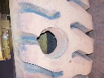
So its time to give some real world meaning to the theoretical idea. I have done the CJ springs on the back of a chassis, so here are some photos and numbers (note; the chassis is upside down ).
We had some "custom" spring packs made up. CJ-7 front copies in every way, except the eyes suit Suzuki spring bushes . I measured the main seperate from the pack and it was closer to 1125 not the 1130 measurement I did the calculations with. So this setup should result in a more "vertical" shackle position.

So with that 1075mm chassis spacing, and the 1125mm long spring, and a stock 70mm shackle; this is what I hope will be close to ride will look like:

This is a "flat spring", and hence the greatest shackle angle without substantial spring bush failure:

Close up of the shackle at its greatest normal operating angle (I'd say its close to the 37 degrees the theory suggests):

Just by the "look" of it, it does seem to be a reasonable shackle operating angle, maybe a tad flatter than ideal? This vehicle's primary goal will be comfort though, and considering it only has a legal cargo capacity of 250kg, I'm thinking it should achieve its intended properties .
And for JrZook. I did some rough measurments (best I could get by myself and a quickgrip clamp ). At flat the spring is 105mm from the bumpstop (not present in photos). At a shackle position approximately perpendicular to line "c", the spring pin hole is 250~260mm from the bumpstop. I wasn't able to get the spring shackle into a -30 degree position by myself, hold it there and take a measurement . Also Dan, post up how you did your theoretical wheel travel calcs  . I think it would be useful to re-apply that concept for theoretically required shock lengths . _________________ Clearance Hole Technology
|
|
|
|
|
|


