| Author |
Message |
JrZook


Joined: Tue Aug 08, 2006 11:30 pm Posts: 5517 Location: Holland Park
Vehicle: Awesome!!

|
 Posted: Fri Aug 19, 2011 3:17 am |
|
Hahhaha cheers!! Nice pic!
If anything when I go to rebuild this bike I would like to reduce the rake and trail to get it to turn in a little better and become more stable through the corners.
Also would like to machine down the inner fork tubes so I can drop the front rideheight down an inch or so more. No wanky ape hanges and super rake for me, I want it to handle  _________________ Lil Foot!
http://tiny.cc/gtsw1
|
|
|
|
|
shakes

Joined: Sat Apr 10, 2010 11:30 pm Posts: 4895 Location: Northcote
|
Posted: Fri Aug 19, 2011 3:45 am |
|
|
This may be of some use to you... Especially if your going to go to that extent. I havent gotten too far into my research yet so I have no idea how accurate it it is.
Found it on an old cafe racer website and lost the original link in my great hard drive crash of 2010.
You do not have the required permissions to view the files attached to this post.
|
|
|
|
|
JrZook
Joined: Tue Aug 08, 2006 11:30 pm Posts: 5517 Location: Holland Park
Vehicle: Awesome!!
|
Posted: Fri Aug 19, 2011 3:53 am |
|
|
|
|
4wheeljive
az supporter


Joined: Mon Nov 02, 2009 10:30 pm Posts: 315 Location: Ballina
|
Posted: Fri Aug 19, 2011 10:11 am |
|
|
So what's next more testing of the digi ignition or on to the fuel injectors
|
|
|
|
|
JrZook
Joined: Tue Aug 08, 2006 11:30 pm Posts: 5517 Location: Holland Park
Vehicle: Awesome!!
|
Posted: Fri Aug 19, 2011 12:35 pm |
|
|
Well imma still waiting for my intake manifold so no injection as yet but the code for that is pretty much written. So once I get the manifold the fuel injection side of things won't be far off!
Implemented a 2 stage rev limiter since I found out the stock ignition module doesn't have anything at all. With the exhaust this engine revs freely until it starts to valve bounce!! First stage kicks in at 8000RPM which retards the ignition to about 10BTDC. Second stage is a full spark cut at 8500RPM. First stage seems to nicely slow down power delivery before the second hits. Works well!
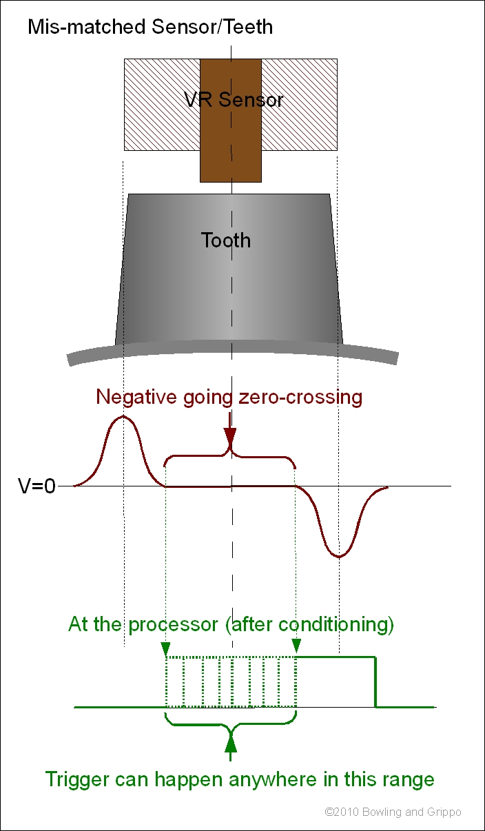
Unfortunately I have discovered a fundamental design flaw between my system and the Yamaha setup that I will have to attend to. The teeth on the flywheel are roughly 10mm in length, where as the reluctance sensor core is roughly 5mm diameter. Due to these miss-matched lengths my zero crossing trigger fluctuates quite drastically over the tooth length thus throwing the timing out over the RPM range.
Yamaha must use some sort of voltage comparator which triggers off the trailing edge of the tooth. This approach will still skew the timing slightly against RPM but not near as much as what I have setup atm. From a design perspective, a zero crossing trigger with matched tooth/sensor widths provides the best timing accuracy and this was teh approach I was taking. Unfortunately the miss-matched widths have killed that accuracy..
So I will need to come up with another approach. Either I set up some sort of voltage comparator and trigger such as Yamaha do or I work out some way of getting the teeth/sensor widths matched. Hurmmmmmm.....
_________________ Lil Foot!
http://tiny.cc/gtsw1
|
|
|
|
|
Rhinoman
Joined: Mon May 16, 2011 7:03 pm Posts: 686 Location: Brinkworth, England
|
Posted: Sat Aug 20, 2011 6:20 pm |
|
JrZook wrote: Unfortunately I have discovered a fundamental design flaw between my system and the Yamaha setup that I will have to attend to. The teeth on the flywheel are roughly 10mm in length, where as the reluctance sensor core is roughly 5mm diameter. Due to these miss-matched lengths my zero crossing trigger fluctuates quite drastically over the tooth length thus throwing the timing out over the RPM range.
Have you got a scope capture of that?
_________________
2000 Suzuki Vitara 1.6 8V
1986 Suzuki SJ413K
|
|
|
|
|
Damo
az supporter

Joined: Sat Jul 22, 2006 11:30 pm Posts: 4661 Location: Brisbane
|
Posted: Sat Aug 20, 2011 8:52 pm |
|
JrZook wrote: Unfortunately I have discovered a fundamental design flaw between my system and the Yamaha setup that I will have to attend to. The teeth on the flywheel are roughly 10mm in length, where as the reluctance sensor core is roughly 5mm diameter. Due to these miss-matched lengths my zero crossing trigger fluctuates quite drastically over the tooth length thus throwing the timing out over the RPM range.
Yamaha must use some sort of voltage comparator which triggers off the trailing edge of the tooth. This approach will still skew the timing slightly against RPM but not near as much as what I have setup atm. From a design perspective, a zero crossing trigger with matched tooth/sensor widths provides the best timing accuracy and this was teh approach I was taking. Unfortunately the miss-matched widths have killed that accuracy..
What's stopping you using the Yamaha sensor?
_________________
SJ50.4.LYF
|
|
|
|
|
JrZook
Joined: Tue Aug 08, 2006 11:30 pm Posts: 5517 Location: Holland Park
Vehicle: Awesome!!
|
Posted: Sun Aug 21, 2011 12:49 am |
|
|
Rhinoman: I'll grab a scope capture so I can show the actual issue.
Damo: I'm using the stock yamaha VR/flywheel setup. Yamaha seem to trigger off the trailing edge of the waveform which is reference to 8* BTDC. I'm trying to detect a zero crossing, not an edge and thus the missmatched sensor/tooth widths may be causing my issue
_________________ Lil Foot!
http://tiny.cc/gtsw1
|
|
|
|
|
JrZook
Joined: Tue Aug 08, 2006 11:30 pm Posts: 5517 Location: Holland Park
Vehicle: Awesome!!
|
Posted: Sun Aug 21, 2011 1:17 am |
|
Even better! Found exactly what I was trying to explain on the megasquirt site. This is also how my CRO scope looks like.
 _________________ Lil Foot!
http://tiny.cc/gtsw1
|
|
|
|
|
Damo
az supporter
Joined: Sat Jul 22, 2006 11:30 pm Posts: 4661 Location: Brisbane
|
Posted: Sun Aug 21, 2011 2:30 am |
|
JrZook wrote: Rhinoman: I'll grab a scope capture so I can show the actual issue.
Damo: I'm using the stock yamaha VR/flywheel setup. Yamaha seem to trigger off the trailing edge of the waveform which is reference to 8* BTDC. I'm trying to detect a zero crossing, not an edge and thus the missmatched sensor/tooth widths may be causing my issue
Yep ok. You mentioned that in the original post. Reading fail on my part 
_________________
SJ50.4.LYF
|
|
|
|
|
JrZook
Joined: Tue Aug 08, 2006 11:30 pm Posts: 5517 Location: Holland Park
Vehicle: Awesome!!
|
Posted: Wed Aug 24, 2011 2:28 pm |
|
Here we have a capture of a tooth passing the reluctor pickup and its resulting voltage signal.

The issue does not immediately jump out at you until I zoom in a bit and re elaborate that I was triggering off a zero crossing.

As you can now clearly see, there is no sharp distinct zero crossing from the waveform. It stays around 0v in this case as the CRO cursors show 1.96ms. Thus with any little bit of electrical noise, the trigger canoccur anywhere where the signal is hovering at 0V. Not good! This was the cause of the timing fluctuations with RPM!
I resorted back to the stock flywheel setup to work out exactly how the stock system sorted this out. The stock flywheel has only a few timing marks on it. One for each of the cylinders TDC, and another 2 that corresponded to ~5* and 8*BTDC for CYL1. I worked out a few more markings using the circumference between TDC1 and TDC2 (60 degrees).


First thing to note is that the trailing edge on the tooth representing cylinder 1's crank phase corresponds to the 8*BTDC mark on the flywheel. The tooth width corresponds to roughly 11*. I was basing my system of a zero crossing thinking it would relate to TDC. In this case it would relate to 8+(11/2) = 12.5* BTDC. I didn't have and crank angle offset dialled into my ECU therefore setting 8* BTDC was in fact 8+12.5* BTDC + any zero crossing fluctuations I was encountering! Waayyyyy off!!
Using this info, I rigged up a simple level detecting comparator circuit with a RC input filter. I set the bias up to trigger once the reluctor input was ~+0.7V above ground to trigger off the trailing edge of the tooth. Ended up pulling the crankcase cover off the bike and punching a few more timing marks into the flywheel at 10-15-20-25-30*BTDC to check the physical timing accuracy. Threw it all back together and chucked the timing light back on. WIN!!! So far anyway. The timing light showed very close to spot on physical timing to what was dialled into the ECU. Have yet to ride the bike again with these mods.
While I had the stock TCI off I decided to pull it apart and throw it on the spin bench so I could probe it to see how it conditioned the input signals. It seems to use a simple level detecting system such as I implemented. Most likely by the look of it, a 2 transistor Schmitt trigger setup.


I just have to try and filter this input signal a bit more but adding some more hysteresis into my level detector circuit and I think I may have nailed it  _________________ Lil Foot!
http://tiny.cc/gtsw1
|
|
|
|
|
Jazzor
az supporter

Joined: Sat Jul 24, 2010 4:42 pm Posts: 502 Location: Kingston, Tas
Vehicle: 85 Suzuki Sierra
|
Posted: Thu Aug 25, 2011 6:52 am |
|
Very impressive!, mad smile on my face reading this  .
I have learnt a bit about how efi bikes work too. I have a ktm 690 duke and just play with uploading new maps other people made onto the computer, but you go into a lot of detail about how the computer gets signals from the engine, very cool!
Hopefully you get to go for a ride again soon _________________ Orange LWB Sierra
|
|
|
|
|
Rhinoman
Joined: Mon May 16, 2011 7:03 pm Posts: 686 Location: Brinkworth, England
|
Posted: Thu Aug 25, 2011 10:50 am |
|
Can you read the part number on the processor they used?
_________________
2000 Suzuki Vitara 1.6 8V
1986 Suzuki SJ413K
|
|
|
|
|
JrZook
Joined: Tue Aug 08, 2006 11:30 pm Posts: 5517 Location: Holland Park
Vehicle: Awesome!!
|
Posted: Thu Sep 08, 2011 2:45 pm |
|
|
Hey James,
Managed to read teh part number off the processor:
D131850 - 0570
76C40AP - 0161
JAPAN 0237EAI
H0524MAA
it's a 40pin DIP. Do you know what it is?
They also use a Toshiba TA8000s inline 5V reg with watchdog timer and Sanken 2SD2141 darlington power transistors for the ignitors.
The test filter/trigger circuit I sent you failed once again so I'm currently having a dig through this Nippon circuit to see how they sorted it out. So far it seems fairly simple.
It's the EMF I believe from the coils firing which is introducing noise into the trigger circuit and causing false triggers.
I'm using IRF840 MOSFETs as my ignitors in which I believe have built in avalanche protection diodes in them.
Dan
_________________ Lil Foot!
http://tiny.cc/gtsw1
|
|
|
|
|
Rhinoman
Joined: Mon May 16, 2011 7:03 pm Posts: 686 Location: Brinkworth, England
|
Posted: Thu Sep 08, 2011 3:06 pm |
|
The processor is an odd one, I've never found any manufacturer's data for the 76C series andthe only clue that I have is one Aisin Warner PCB that had TMP76C40 on the silkscreen under the chip which seems to indicate that its a Toshiba device.
Does it have a 12MHz crystal? other than its odd clock set up it is to all intents and purposes a 6801/6301 clone and the memory can be read the same way using special test mode.
It seems to be the granddaddy of what is commonly known as the MH series of processors although I've only seen them marked as Mitsubishi devices.
Check out my info here:
http://www.rhinopower.org/ECUs/RomReader/Romreader.html
_________________
2000 Suzuki Vitara 1.6 8V
1986 Suzuki SJ413K
|
|
|
|
|
Rhinoman
Joined: Mon May 16, 2011 7:03 pm Posts: 686 Location: Brinkworth, England
|
Posted: Thu Sep 08, 2011 3:09 pm |
|
JrZook wrote: Hey James,
It's the EMF I believe from the coils firing which is introducing noise into the trigger circuit and causing false triggers.
'm using IRF840 MOSFETs as my ignitors in which I believe have built in avalanche protection diodes in them.
Dan
If you think that it works pretty well except for that then I would just concentrate on the new PCB layout. Get that right and your problems may disappear. that siad please publish the Denso circuit, I am interested to see how they handle the hardware.
_________________
2000 Suzuki Vitara 1.6 8V
1986 Suzuki SJ413K
|
|
|
|
|
JrZook
Joined: Tue Aug 08, 2006 11:30 pm Posts: 5517 Location: Holland Park
Vehicle: Awesome!!
|
Posted: Thu Sep 08, 2011 3:56 pm |
|
Yea the processor seems odd. No info at all on that one! It does run a ceramic resonator at 12MHz, which to me is a bizarre frequency to run at.
The IRF840's with their built in avalanche diode, do you think they require external snubbing circuitry or flyback diodes or would the be internally snubbed and protected?
These are the issues I'm trying to sort out to make the next board, so I get the hardware hopefully spot on this time. The first board was really a training exercise to find out what I missed and require on the new one.
This is the Denso input conditioning circuit which seems to be fairly simple but works really well at least in spice with simulated noise. The simulator shows even better results then my last circuit using the comparator and a descent amount of hysteresis.
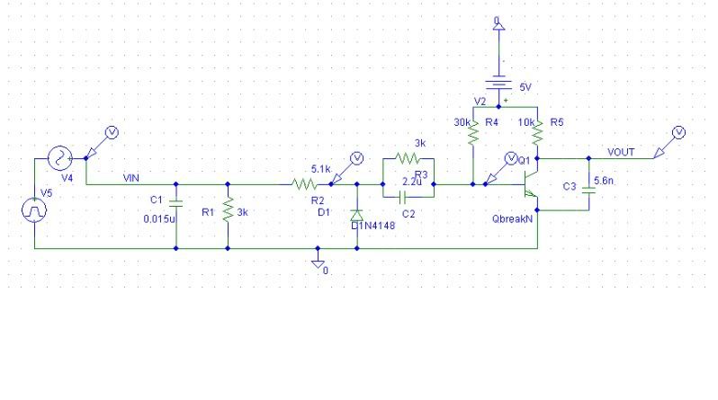
I'm going to have to give this one a go anyways since it seems to work for denso, it should also work for me.
Do you know the function of the parallel C2 and R3 components? IS it some sort of 'quickerer' to turn the base off faster? I've seen it used in a few circuits before.
I also stumbled across this very simple VR conditioner circuit which seems to work for this production unit:

Looks to me like those LP RC filters in it would introduce a descent phase delay from the VR signal to the micro...
Dan _________________ Lil Foot!
http://tiny.cc/gtsw1
|
|
|
|
|
Rhinoman
Joined: Mon May 16, 2011 7:03 pm Posts: 686 Location: Brinkworth, England
|
Posted: Thu Sep 08, 2011 4:57 pm |
|
|
The first circuit I've seen used a few times before, its a fairly crude set up and you will get timing changes with both RPM and with temperature so you'll need to compensate in software.You'll need adequate decoupling of the 5V supply too because any excess voltage will be dumped into the 5V rail. The negative going swing will be dumped into the ground so that needs to be a good return to battery to have a solid return path too.
The second image doesn't show.
_________________
2000 Suzuki Vitara 1.6 8V
1986 Suzuki SJ413K
|
|
|
|
|
Rhinoman
Joined: Mon May 16, 2011 7:03 pm Posts: 686 Location: Brinkworth, England
|
Posted: Thu Sep 08, 2011 5:18 pm |
|
|
The second circuit has a HPF and an LPF, it looks more like its for speed detection rather than position detection and over a limited range. Curiously the input goes to an ADC pin as well as what we can only assume to be an IC or other interrupt pin.
The 12MHz resonator is because the clock frequency is divided by 6 to get the E clock which then gives a fairly common 2MHz bus frequency, equivalent to an HD63B01. I would have expected a crystal but I guess that because its fairly low powered the timing isn't that critical.
You may find that the circuit is designed so that the advance generated by the input stage is used to control the timing in 'limp-home' mode. The output from the watchdog may control a mux.
_________________
2000 Suzuki Vitara 1.6 8V
1986 Suzuki SJ413K
|
|
|
|
|
PJ.zook
az supporter
Joined: Sat Oct 24, 2009 10:30 pm Posts: 845 Location: Melbourne
|
Posted: Thu Sep 08, 2011 9:00 pm |
|
|
So how'd you solve the icing problem?
|
|
|
|
|
JrZook
Joined: Tue Aug 08, 2006 11:30 pm Posts: 5517 Location: Holland Park
Vehicle: Awesome!!
|
Posted: Fri Sep 09, 2011 1:35 am |
|
Rhinoman wrote: The first circuit I've seen used a few times before, its a fairly crude set up and you will get timing changes with both RPM and with temperature so you'll need to compensate in software.You'll need adequate decoupling of the 5V supply too because any excess voltage will be dumped into the 5V rail. The negative going swing will be dumped into the ground so that needs to be a good return to battery to have a solid return path too.
The second image doesn't show.
Hurmmm do you have any suggestions for a conditioning circuit I could use in this particular case as I have miss-matched tooth/sensor widths thus a true zero crossing IC or detector will not work without inconsistent phase shift?
In regards to the Denso conditioning circuit as you said there will still be some sort of phase shift, how much shift do you think we are talking about? The tooth width is ~10mm which corresponds to ~11* of crank angle and the sensor width is roughly half of that ~5mm.
The other issue with this particular engine is it's coarse crank angular velocity changes especially at low RPM's and low tooth count on the flywheel. This makes estimating the the position of the next tooth an absolute bitch in terms of timing accuracy. I'm currently using a simple averaging algorithm per revolution (updated every pulse) to determine the position of the next but I think I may have to resort to the instantaneous speed of the previous pulse to get better accuracy.
In regards to capacitor decoupling, do you know of any descent links to actually calculate the required caps? Pretty much all that I've seen just state to use a ~0.01uF and 1uF close to the source... _________________ Lil Foot!
http://tiny.cc/gtsw1
|
|
|
|
|
JrZook
Joined: Tue Aug 08, 2006 11:30 pm Posts: 5517 Location: Holland Park
Vehicle: Awesome!!
|
Posted: Fri Sep 09, 2011 1:48 am |
|
|
That second circuit is not very impressive IMO but for some reason it seems to work acceptable. As said it's in a low quantity production ECU model. It is quite possible that there are a few 'fudge' factors written into the firmware to make it work perfectly but all I know is that it implements a very significant phase shift due to the LP and the input cap.
I had a read of that site to work out the other connection to the ADC, and that is basically implemented as a bit of a hack to get around the low amplitude pulses at cranking RPMs. He seems to RT sample the pulses at low speeds with the ADC and use that as phase input for the firmware until it reaches acceptable speeds. Besides the ADC inputs, the others go to the internal comparator in the MCU.
Divide by 6 on the MCU, not very traditional. I've only ever heard of bit shifts ie powers of 2 to get bus frequencies before. 2Mhz bus frequency, must be using something like 2us resolution on the timing. I'm kind of wondering now if they are actually using the watchdog timer to provide the constant 5ms of dwell time to the MCU, in avoidance of more complex firmware.
Do you have a datasheet or pin out of this MCU you believe they are using in the Denso unit?
PJ: Icing issue?
Dan
_________________ Lil Foot!
http://tiny.cc/gtsw1
|
|
|
|
|
Rhinoman
Joined: Mon May 16, 2011 7:03 pm Posts: 686 Location: Brinkworth, England
|
Posted: Fri Sep 09, 2011 6:39 am |
|
|
I'd stick with the comparator circuit although I did use a similar transistor circuit about 20yrs ago in a PIC based ignition. The switching transistor was followed by a schottky trigger to square up the waveform. If you don't have a schottky input into the micro then you need to ensure that you meet the minimum rise time spec.
Fot the phase shift its easiest to run it through the simulator and measure it at different rpms, the frequency that the filter will see will be the equivalent frequency of the pulse rather than the repetition rate.
The watchdog timer will be just a watchdog, its not very accurat, that IC is common in Densos of that era.
I used the datasheet for the HD63B01, other than the clock I didn't find any other oddities, the AW ECU didn't use any of the Hitachi extended instructions but I haven't tested to see if the MCU supports them.
_________________
2000 Suzuki Vitara 1.6 8V
1986 Suzuki SJ413K
|
|
|
|
|
JrZook
Joined: Tue Aug 08, 2006 11:30 pm Posts: 5517 Location: Holland Park
Vehicle: Awesome!!
|
Posted: Fri Sep 09, 2011 8:33 am |
|
Rhinoman wrote: I'd stick with the comparator circuit although I did use a similar transistor circuit about 20yrs ago in a PIC based ignition. The switching transistor was followed by a schottky trigger to square up the waveform. If you don't have a schottky input into the micro then you need to ensure that you meet the minimum rise time spec.
Fot the phase shift its easiest to run it through the simulator and measure it at different rpms, the frequency that the filter will see will be the equivalent frequency of the pulse rather than the repetition rate.
The watchdog timer will be just a watchdog, its not very accurat, that IC is common in Densos of that era.
I used the datasheet for the HD63B01, other than the clock I didn't find any other oddities, the AW ECU didn't use any of the Hitachi extended instructions but I haven't tested to see if the MCU supports them.
Hurmmmm so you reckon the comparator setup will be my best bet ie the circuit I sent you? Also do you know what the effect is achieved by the parallel cap and resistor inline with the base of the denso circuit? Some sort of filter?
The equivalent frequency of the pulse, how would you go about working that one out? I've just been using repetition rates and yea they may work for a perfect sine wave but not for these waveforms.
So it seems that I'm getting the noise on the VR signal due to the switching of the coils. I'm driving them directly via MOSFET. Do you use some sort of snubber circuit around the drive transistors?
Thanks again for sharing your knowledge mate! _________________ Lil Foot!
http://tiny.cc/gtsw1
|
|
|
|
|
Rhinoman
Joined: Mon May 16, 2011 7:03 pm Posts: 686 Location: Brinkworth, England
|
Posted: Fri Sep 09, 2011 9:50 am |
|
JrZook wrote: Hurmmmm so you reckon the comparator setup will be my best bet ie the circuit I sent you? Also do you know what the effect is achieved by the parallel cap and resistor inline with the base of the denso circuit? Some sort of filter?
The equivalent frequency of the pulse, how would you go about working that one out? I've just been using repetition rates and yea they may work for a perfect sine wave but not for these waveforms.
So it seems that I'm getting the noise on the VR signal due to the switching of the coils. I'm driving them directly via MOSFET. Do you use some sort of snubber circuit around the drive transistors?
Thanks again for sharing your knowledge mate!
I'd stick with the comparator. I'm pretty sure that the parallel cap is just there to drive the base negative to turn it off faster.
Each 'peak' from the VR sensor is roughly sinusoidal so imagine that they are all strung together without the cap, thats your 'real' frequency.
A snubber is only necessary if you exceed the avalanche rating of the FET, you would have to measure the voltage and current and then do the thermal transient analysis. A snubber will still dump the back emf into the PCB somewhere so layout is still critical. Some manufacturers have used external igniters which keeps the nasty stuff away from the ECU.
_________________
2000 Suzuki Vitara 1.6 8V
1986 Suzuki SJ413K
|
|
|
|
|
4wheeljive
az supporter
Joined: Mon Nov 02, 2009 10:30 pm Posts: 315 Location: Ballina
|
Posted: Thu Oct 13, 2011 6:11 pm |
|
|
Hi dan
Any updates on the beast ?
|
|
|
|
|
JrZook
Joined: Tue Aug 08, 2006 11:30 pm Posts: 5517 Location: Holland Park
Vehicle: Awesome!!
|
Posted: Thu Oct 13, 2011 11:15 pm |
|
Hey mate!
Nothing overly exciting to report on the ECU scene atm. Currently knee deep designing the next PCB and still waiting on my EFI intake to be finalized.
On the other-hand I have sorted out a way to fairly simply increase the engines capacity up by 14% to 285cc with off the shelf pistons from some chinese bike thing. Just have to get the liners bored from 49 to 52.5mm 
This well defiantly help in the future to get the turbo on song!
Stay tuned!
Dan _________________ Lil Foot!
http://tiny.cc/gtsw1
|
|
|
|
|
4wheeljive
az supporter
Joined: Mon Nov 02, 2009 10:30 pm Posts: 315 Location: Ballina
|
Posted: Fri Oct 14, 2011 5:30 am |
|
|
That's cool.
when you get the pistions installed might be an idea to get them crack tested or something cause as we all know the Chinese aren't real crash hot at this whole cast alloy thing although things are improving
|
|
|
|
|
JrZook
Joined: Tue Aug 08, 2006 11:30 pm Posts: 5517 Location: Holland Park
Vehicle: Awesome!!
|
Posted: Fri Oct 14, 2011 10:22 am |
|
4wheeljive wrote: That's cool.
when you get the pistions installed might be an idea to get them crack tested or something cause as we all know the Chinese aren't real crash hot at this whole cast alloy thing although things are improving
They don't seem to bad but the tolerance between the gudgeon pin and piston is a bit sloppy even compared to my high mile stock Yamaha bits 


 _________________ Lil Foot!
http://tiny.cc/gtsw1
|
|
|
|
|
Rhinoman
Joined: Mon May 16, 2011 7:03 pm Posts: 686 Location: Brinkworth, England
|
Posted: Mon Oct 17, 2011 10:37 am |
|
|
I did a little bit more testing and code analysis on the 76C40 used in the Aisin Warner TCM. It seems that although AW only use pure 6800 instructions the processor is much more capable.
I have found that it runs the Hitachi extended instruction set and has an additional Y index register, it looks like there are some extra timer functions too.
So the processor is quite capable but the AW code is extremely inefficient. My guess is that they used the 76C40 as a straight drop in replacement for the 6801 using existing code.
_________________
2000 Suzuki Vitara 1.6 8V
1986 Suzuki SJ413K
|
|
|
|
|
|


