DISCLAIMER: I am not responsible, and I am not accountable for your actions. If you decide to apply any of the following, and something goes wrong, too freaking bad!
My friend and I had quite a few beers and were interested in finding out how the sierra was running.
My friend and I went to the local pick a part and got a heap of O2 sensors from various cars. As this was just a trial we didn’t want to spend $80 on a new one just yet. We opted to use single wire O2 sensors.
My engine set up.
Engine g13BA 120,000 km. 3” Snorkel, stock exhaust, running BP ultimate 98 RON, using BP-6ES (colder plugs than stock), timing at 12 degrees BTDC (I know I can advance my timing further on 98RON, however 98 isn’t always available).
I am running a Ryco marine fuel filter prior to the fuel pump to separate contaminants and water. I am running a motorbike fuel filter between the fuel pump and carburettor.
Air filter is a Ryco air filter to suit the stock Sierra air box.
Procedure:
The carburettor was rebuilt to factory specifications, and the idle mixture was set by ear, and double checked using very small sprays of Aerostart, to find the point at which the engine would no longer increase in rev/s. Further increasing richness would cause the engine to experience lower rev/s.
Once the carburettor was rebuilt and tuned, I removed the stock exhaust manifold.
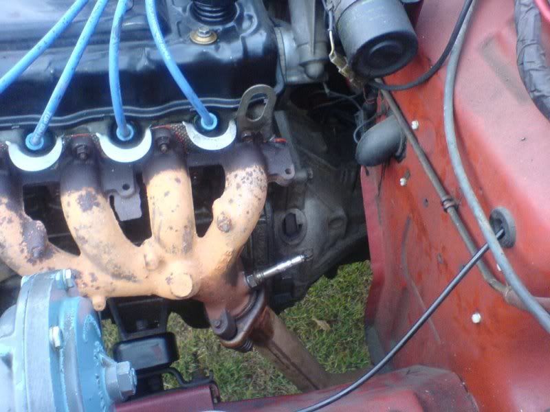
There are two raised circles on the exhaust manifold near the flange coupling.
The first raised circle on the exhaust manifold, points up (towards the locating bracket for storage of the car jack). However this position would only provide exhaust flow data from cylinders 1, 2 and 3, and hence wasn’t used.
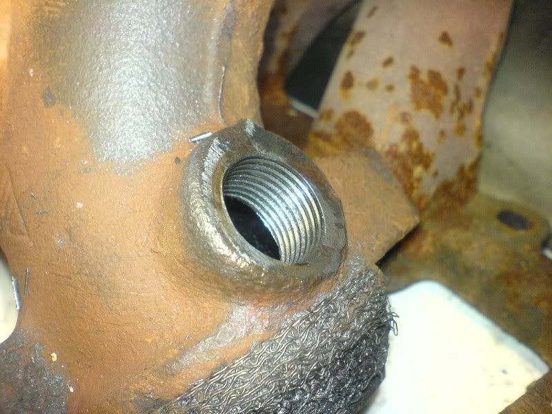
On the bottom of the manifold near the output for the flange coupling, there is a small raised circle with the face pointing towards the firewall (when installed in the car). This is the location where I installed the O2 sensor.
I obtained an 18mm nut with the same thread as the common m18 O2 sensors. Unfortunately the nut was very thick, so I carefully ground this down so it would only cover the thread on the 02 sensor.
Next I drilled a 16mm hole into the centre of the raised circle on the manifold.
So that the O2 sensor with the nut on it would penetrate into the exhaust flow as much as possible, the raised circle was machined down accordingly.
A sacrificial O2 sensor was bolted onto the nut and clamped in place while I welded the nut onto the cast iron exhaust manifold.
Once this was welded and allowed to cool (meaning I had another beer), a better condition O2 sensor was bolted in, and the exhaust manifold was reinstalled.
The signal wire from the O2 sensor was wired into the cab, and onto the multimeter. The single wire O2 sensors use the exhaust/chassis for the earth, so a suitable earth was found and wired to the multimeter.
The car was started, warmed up and taken for a test run.
Multiple O2 sensors were tested, to ensure we weren’t relying on a dud, and they all provided very similar outputs.
The voltage output of the O2 sensor is not linear, and as the oxygen levels approach lambda 1 (14.7:1), the voltage rate of change is very significant. 0.45V is ideal, however as you can see from the results below a reading of 0.9V (rich conditions) is still relatively close to lambda 1.
O2 sensor outputs are as follows
Idle - 0.9V
Part Load - 0.8V
Wide Open Throttle - 0.85V
Stoichiometric Values (actual mass air/actual mass fuel)/(Ideal mass air/Ideal mass fuel). Ideal Stoichiometry is 1
Idle - 0.94
Part Load - 0.993
Wide Open Throttle - 0.99
Air Fuel Ratios (mass air: mass fuel)
Note the ideal air fuel ratio is 14.7:1
Idle - 13.8:1
Part Load - 14.6:1
Wide Open Throttle - 14.5:1
I found if I applied a small tap on a vacuum line and allowed a very small amount of air to enter the manifold I could actually obtain lambda 1, whilst the engine was revving through the range under no load.
Anomalies:
I found that when you back off the throttle, there is a tendency for the engine to briefly run lean (which is as expected).
When the throttle is applied the engine runs slightly rich (which is as expected, due to the little pump which squirts fuel directly into the throttle body as the throttle opens).
It is interesting to note how well the stock Suzuki carburettor is performing. I have read comments where people are stating that;
The engine runs lean at WOT and it is why the engines burn out etc. This I feel is incorrect.
Changing to EFI will greatly improve fuel economy, results point that this too is correct. On a stock carburettor set to specifications, operates pretty well for 20+ year old technology.
EFI enters closed loop under partial throttle, where it increases and decreases the air fuel ratio based on feedback from the O2 sensor. At WOT throttle EFI system enters open loop state, where it dumps fuel in based on MAP and throttle position only (similar to a carburettor). The only real benefit to EFI would be during start up, where the choke allows the engine to run rich, however I found that the engine doesn’t run overly rich anyway.
I feel changing to single port EFI would offer little to no increase in power or efficiency, due to the very good performance of the carburettor. Providing the intake systems are properly filtered and set to specifications, I would suspect the stock sierra carburettor nightmares will be a thing of the past.
Toyota documentation indicates that;
Best fuel economy is obtained at 0.04V, an AFR of around 16:1.
Best power is found at an air fuel ratio of 12.6:1, which would read 0.93V.
If improved fuel economy is the goal, you could adjust the idle jet mixture screw, making it leaner (AFR of 16:1). The majority of the fuel efficiency factors in city driving is the idle mixture.
If increased power is the goal, you could rejet the secondary jet to obtain the AFR of 12.6: at WOT.
Doing both of these would provide the best power at WOT, yet good fuel economy at idle and partial load, the primary jet can be left untouched as I feel it’s performance is quite satisfactory.
From my own experience carburettor issues occur in extremely dusty conditions or with water, where my assumption is that particulates are by passing the crappy old seals/filters. Angles haven’t proven to be any issue, and I haven’t experienced any surging issues except after dusty/lots of water.
I found the aged stock seals and arrangements were insufficient, allowing particulates to enter the air box, carburettor throat.
The largest problem with the carburettor has been the fuel bowl breather, which is the piece of brass pipe which is oval cut with the opening facing the top of the carburettor in the secondary throat. If a little piece of grit bypasses the filter/seal arrangement and enters this pipe, it then passes into the fuel bowl and into the jets. Which causes head aches. Unfortunately this pipe is required to face into the air stream, as to increase the static air pressure in the fuel bowl whilst the secondary jet is open.
It may be possible to block this breather pipe off, and then drill and tap a fitting in the top of the carburettor and place the pipe, filter and hose into the air intake system elsewhere, where it can obtain the static pressure required, without any issues regarding the air flow obstruction in the secondary carburettor throat. However, If this nozzle was relocated and place elsewhere in the intake system, it would have the effect of increasing the static pressure for all conditions, similar to incorrectly set fuel float levels. Another alternative to avoid the particulate contaminants entering this breather needs to be investigated, so we can achieve the same static pressure as required for WOT, whilst keeping the air which flows through here filtered.
As I have since obtained multiple sierra carburettors in need of maintenance (for very cheap), I will rebuild and modify one, and let you all know how this goes.
My other setups to avoid carburettor nightmares, however if I had EFI I would probably do the same thing, ensuring the fuel and air systems are clean.
I am planning to obtain an oiled sock filter to install inside the snorkel head.
The air box is fully sealed, with a larger hole drilled into the bottom with piping and a tap for the drain (open and close this manually, so I don’t fill my air box with water during deep swims).
The stock filter is sealed to the air box, both on the top and bottom using Silastic.
The air box lid is sealed using Silastic, and the air pipe to top of the carburettor is sealed using Silastic.
Pressure loss due to multiple air filters is overcome by the use of the ram air effect generated by the snorkel head. A few people with some knowledge will argue that at 100 km/h the pressure created by snorkels are very low, and not worth it. However, the air flow over the snorkel head is much greater than 100 km/h, when the vehicle is doing 100 km/h. This is because of the aerodynamics of the vehicle causing the air speed to increase as it passes over the bonnet, windscreen etc.